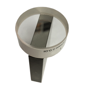
Optical flats are used to test the flatness of fine-lapped surfaces such as the measuring faces on gauge blocks, measuring inserts, measuring tables, micrometers etc., which have to meet extremely high demands on accuracy. Interference fringes appear when the optical flat is laid on the surface to be tested. Their number shape and configuration make it possible to identify geometric deviations in form on the surface.
The interference fringes are caused by the nature of light waves. They appear when a thin wedge of air is formed between the glass surface and the surface to be tested. incidental light is reflected and split into two partial beams, which become superimposed due to the different frequencies and thus produce interference fringes. When daylight is used (i.e. light with various wave lengths), the fringes are coloured. With monochromatic lights (i.e. light with only one wave length), alternate light and dark fringes appear. The distance between the fringes is determined by the width of the air wedge.
If the surface tested is flat, the fringes are straight and parallel to the corner edge. An uneven surface shows curved fringes, e.g. circular if the surface tested is concave or convex. The deviation in size of the distance between two fringes of the same colour corresponds to an error in flatness of hale a wavelength of the colour used. This value is approx 0.3 um for daylight.

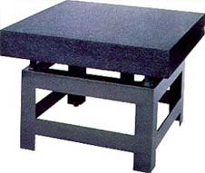
Surface plates (BS 817:2008) are used as a datum surface on which to make measurements. There are 2 types of surface table:
Both of these are available in 4 grades:
Example 1: (using BS817:2008 table 1)
1000mm x 630mm table:
| Grade | Variation | Overall Flatness |
| 0 | 0.003mm | 0.0055mm |
| 1 | 0.006mm | 0.011mm |
| 2 | 0.012mm | 0.022mm |
| 3 | 0.024mm | 0.044mm |
The surface plate is measured using a sensitive electronic level following either a union jack method or a grid method:
Lines are drawn on the surface table that mimic those of the union jack flag. The electronic level is then moved down each line at predefined spacing recording the angular changes at each position. Flatness calculations are then made electronically using this information.
Lines are drawn on the surface table in a grid pattern. The electronic level is then moved down each line at predefined spacing recording the angular changes at each position. Flatness calculations are then made electronically using this information
In addition to both these methods, local variations in flatness are also checked using a variation gauge.
Rhopoint Metrology Ltd Eurolab House, Unit 10 Valepits Road, Garretts Green Industrial Estate, Birmingham, B33 0TD
Rhopoint Metrology Ltd Brunel House, 28 Old Mills Industrial Estate, Paulton, BS39 7SU